INTRO
If you would like to separate your broadcast domain to 2 vlans
(or more) then this article is for you. This article builds off of the foundation discussed in this Layer 2 VLANS article. You can do that with a Layer 2 switch and a router (which you should already have). I dont have a step by step UI guide, I only give you the outline of the steps. Its up to you to figure out how to use the UI (the software manual is a great starting place, or if your like me you can just tackle it head on)
EXAMPLE / THE GOAL
In this example the goal is to take 1 network and separate it to 2 vlans. One for IT and one for EVERYONE else. We will call the IT network vlan 10. And the EVERYONE else network vlan 20.
If your router understands VLANS: the end result will be 2 broadcast domain. Each network will have its own subnet. Such as 10.10.0.x and 10.20.0.x for vlan 10 and 20 respectively. Traffic will be separated on Layer 2 and Layer 3. This is alike to Cisco Lessons of router on a stick. Where your switch has 2 vlans, and the router does the routing for 2 vlans. I will highlight items related to this with light blue.
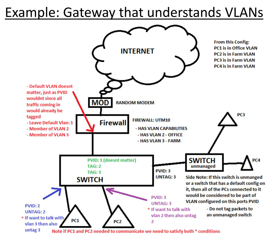
Caption: Switch Vlan Config With VLAN AWARE ROUTER. View full article at: http://www.infotinks.com/netgear-vlans/
If your router does NOT understand VLANS: the end result will be 2 broadcast domains. Each network will be in the same subnet. So every PC will be in 10.10.0.x. However traffic will be seperated on Layer 2. Albeit, You can jerry-rig each VLAN to have different IPs, on the router you will just need to set 2 IPs on the same interface (this is called multihoming, or simply having a primary IP and a secondary IP, it doesnt matter which network has the secondary IP or vice versa). I will highlight items related to this with light yellow.
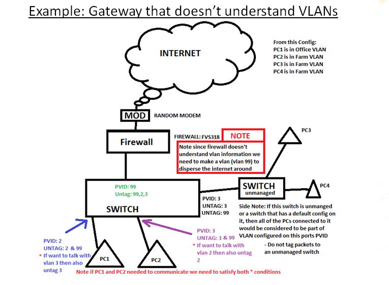
Caption: Switch Vlan Config With VLAN UN-AWARE ROUTER. View full article at: http://www.infotinks.com/netgear-vlans/
Configuring Yellow on Blue: Also note that if your router does understand VLANS you can still use the configuration for “Routers that dont understand vlans”.. Simply dont make the VLANS on it and follow the steps for “Router that doesnt understand vlans”.
LEARN THESE TERMS
Follow along with this infographic captures the basic concepts of tagging/untagging/pvids with 802.1q vlans & how it operates to frames traveling thru these switches (more of this is explained above)
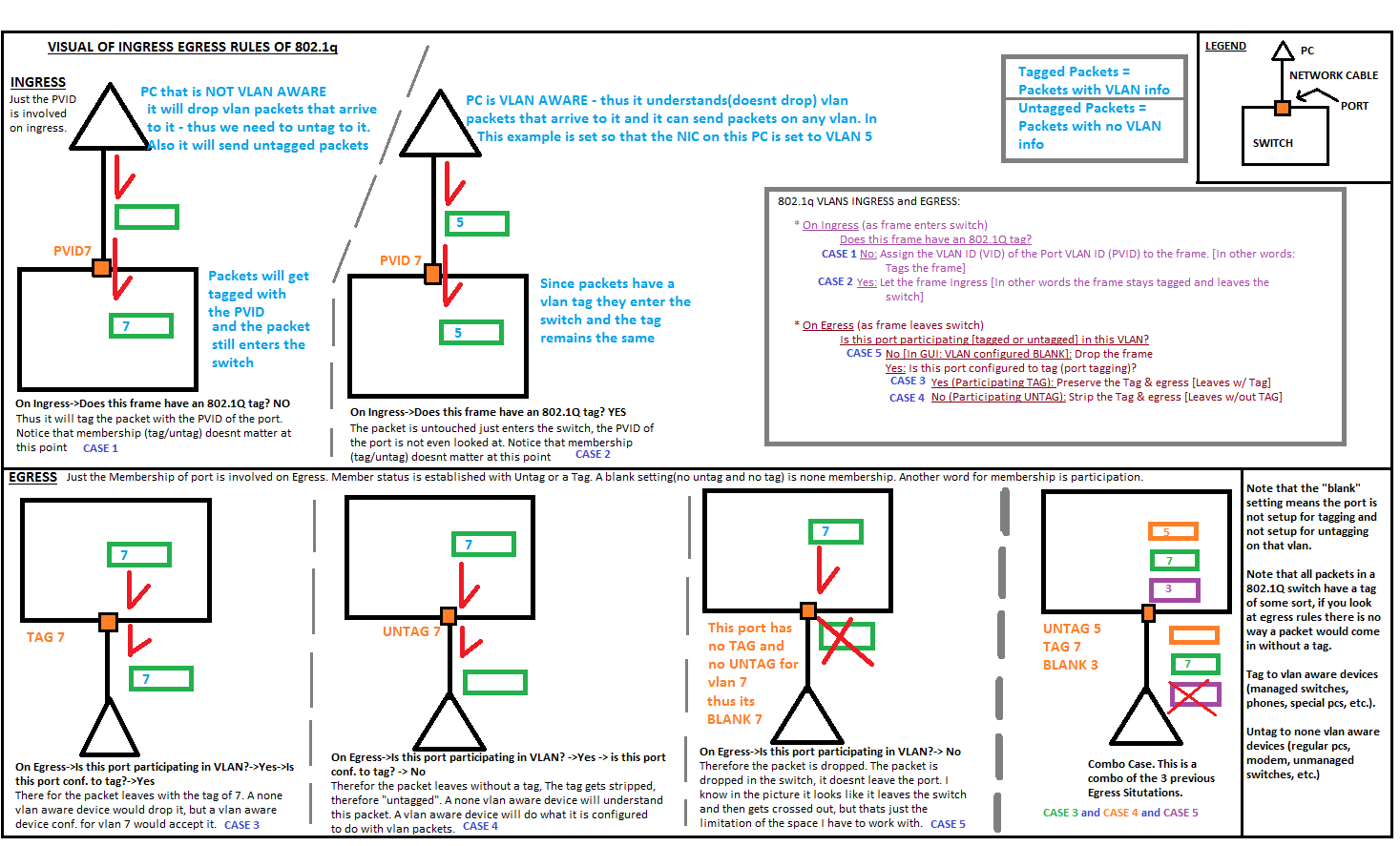
Caption: How 802.1q Works. View full article at: http://www.infotinks.com/netgear-vlans/
- Frame: When packets operate on a Layer 2 level of the OSI model they have been broken down into a Frame/Ethernet Frame.
- 802.1q VLANS: we will be setting VLANS by putting a VLAN tag on the packets/frames – tags can be removed and added to a packet/frame (this introduced Tagging/Untagging/PVID). There is another concept of Port based VLANS which basically seperates packets/frames based on which port they arrive on, there is no packet/frame manipulation of adding or removing tags with Port based VLANS. Port Based VLANS are very limited and are not used anymore. We can achieve “Port Based” VLANS type of behavior with 802.1q – which I will show here. PCs on certain ports will be bound to a certain VLAN based on which PVID we give them
- Tagging: Ports set to Tag VLAN #x will allow packets/frames to leave out that port if they have the VLAN #x tag on them. On the way out of the switch the tag will stay on. This is prefered if you want to send the packet to another VLAN aware device (such as a switch or a VOIP phone or a router that understands VLANs). Tag = Exit with Tag.
- Untagging: Ports set to UnTag VLAN #x will allow packets/frames to leave out that port if they have the VLAN #x tag on them. On the way out of the switch the tag will be stripped off. Computers and none vlan aware devices need to receive untagged packets as they dont understand VLAN tags (unless they have special interfaces that have that feature). Common ports to untag on: PCs, Routers, Gateways / Firewalls, TVs, Internet = Modem. These are not strict, there are plenty of PCs and Routers & Firewalls that support VLANs. Untag = Exit without Tag.
- PVID: Packets/Frames entering the switch without any VLAN identifier on them (without a tag) will be tagged with the PVID. The end result is that every packet/frame inside of the switch is tagged with something. Ports cant have a blank PVID, I mean technically they can, but Netgear / HP switches have a default PVID of 1. That means inside a factory defaulted switch all packets/frames have a tag of 1, but that doesnt matter as on the way out they are all untagged 1 (so that is removed) – its as if the frames were never changed with.
- Blank Port: What if a port doesnt have a TAG or UNTAG for a specific VLAN #? Then packets that have a certain VLAN # attached to them (tagged to them) will not leave out of that port. Blank Port = No Exit.
- Router: Here I call the next hop from the PCs the ROUTER. This ROUTER is also your gateway to the internet (well in this case, in real life you could have a router going to another network but not to the internet). So this ROUTER of ours does ROUTING, NAT (so its a good DEFAULT GATEWAY and also it acts as a STATEFUL FIREWALL for connections). The words ROUTER/GATEWAY/FIREWALL get interchanged lots of time. Lets clear that up. Usually when people say ROUTER, they are talking about their ROUTER which also has the ability to do NAT (which makes it the INTERNET GATEWAY – what is NAT?). Now adays any router that does NAT also automatically will also have the ability to be a FIREWALL (so that it can block certain traffic, or forward certain traffic using port forwards or port triggering). Not all routers have to do NAT. Some Routers can connect different Layer 3 networks together and dont neceserally have to do NAT as well. Business’s with giant Networks that have multiple subnets utilize routers to connect the different Layer 3 networks together. LAYER 3 SWITCHES (Very expensive devices) can do the same tasks as ROUTERS. In this article we are talking about LAYER 2 SWITCHES.
- /24: This means a subnet mask of 255.255.255.0. Sometimes I want to save time writing so I type /24. This is regular convention.
THE DETAILED STEPS
Here is an example written out step by step using VLAN 10 and 20.& 99 (for internet, if the router doesn’t understand vlans). These steps are written out in a tree fashion as you might go a different route (there is a different set of steps if router understands vlans versus if it does not). In my infographic (see above) I use VLANS 1,2,3 (this goes against my thumb rule of NOT using VLAN #1 and for that matter VLANs numbered 1 thru 10 – as those can be used by vendors for vendor specific mappings)
Im assuming the switch here is strictly a Layer 2 switch. Meaning you cant set IPs on its VLANs so your cant have VLAN routing on it. If you have a Layer 3 switch which does support IPs on its VLANS, you can take away that functionality by not enabling “ip routing”.
- First find out if your router supports VLANS (If it supports vlans then it understands vlans). If it does or doesn’t will change your configuration on some ports (you will need to tag or untag differently or set different pvids at different ports).
- If the router does understand vlans (VLAN AWARE) then you will not need to make an extra VLAN on your SWITCH (Notice the light blue highlights) – see infographic above
- PROS: Each VLANS local and internet traffic is seperated. Less work. You can optionally setup Intervlan communication so that unicast traffic can jump (by routing) vlans at the router – in this case the broadcasts and multicasts are still limited to their broadcast domain (they wont jump vlans)
- CONS: Each VLAN will need to be a in a different L3 subnet (for example VLAN 10 is in 10.10.0.x/24 and VLAN 20 is in 10.20.0.x/24). Its not really a big CON. But that means we also need to have 2 DHCP pools if we want DHCP. THat means our ROuter better support DHCP. Well if its supports VLANS most likely it also support DHCP to those VLANS.
- You will need to make sure both of your VLANS are created on your Router
- On the Router make sure you have both VLANS created and you give both VLANS an IP and SUBNET and also a VLAN NUMBER (we will use 10 and 20). So a Good IP would be 10.10.0.1/24 for VLAN 10 and 10.20.0.1/24 for VLAN 20. (/24 meaning subnet mask is 255.255.255.0)
- The PCs on each VLAN will point at these IPS as their GATEWAY address. Example: a PC in VLAN10 will have its GATEWAY IP set to 10.10.0.1 and SUBNET MASK 255.255.255.0. Its actual IP will just need to be 10.10.0.100.
- The Router will allow intervlan communication (sometimes thats enabled by default and sometimes you will need to configure that). On Netgear Routers its as simple as checking “Intervlan Communication” on both of your VLANs. Broadcast & Multicast traffic will not be intervlan communicated.
- This setup is alike to “Router on a Stick” with Cisco, where the switch has the 2 VLANS configured. The Router also has the 2 Vlans.All of the routing that needs to be done needs to go from the PCs to the Switch and then to the Router and from there it can go to the internet or back to the switch if its heading to another VLAN. Traffic within the same VLAN will stay on the switch.
- If the router does not understand vlans (VLAN UNAWARE ROUTER) then you will need to make an extra VLAN on your SWITCH (Notice the light yellow highlight) – see infographic above
- CONS: Your internet traffic on each VLAN is not separated (well all of a PCs Returned internet/router traffic could be recieved on a port that doesnt belong in the PCs vlan). But local traffic is separated in the broadcast domain (as requested). More work as you have to make another VLAN. You cannot setup Intervlan communication as there is no routing between the 2 vlans.
- PROS: Both of your VLANs can be in the same Layer 3 Subnet, yet they will be in different Layer 2 Subnets so they wont communicate on the Local traffic. The router, if it has a DHCP server, can server IPs to both of your VLANS (since traffic from the router will be able to go to both VLANs)
- If your router supports VLANS but you want to do this configuration you can. Just configure everything on its main default VLAN and dont create any VLANS. Make sure all of the traffic out of the router is UNTAGGED.
- On your Router you will need to create an extra VLAN called “INTERNET” vlan and give it some number like 9
- Untag 99 on all ports (specifically on the ports going to IT and EVERYONE pcs).
- Tag it on ports going to other switches that need to carry the internet LAN.
- On the port going to your router, set its PVID to 99
- Each PC has to have a Default Gateway set to the IP address of the Router. Each PC has to have an IP in the same subnet as the router. So if the Router has an IP of 10.10.0.1 / 24 then each PC in either VLAN has to be 10.10.0.x /24. Even though PCs in different VLANS have the same Layer 3 subnet (they are all in 10.10.0.x) their traffic is still separated on layer 2 so there is no worry about communication interchange (except for returned internet/router traffic as discussed in the CON section and later on in the article)
- Another trick: If you do want to have each VLAN to have different IPs (different L3 subnet), You can do that. You can do whatever you want to the IPs, as long as there is IP routing (as long as the router does what its supposed to). All that needs to be done is give the router 2 IP addresses in place where it usually had 1 IP address (also known as Multihoming, also this is called giving a secondary IP address). So the primary/main IP can be 10.10.0.1/24 and the secondary ip can be 10.20.0.1/24. Then Give PCs in VLAN 10, IPs in the subnet 10.10.0.x/24 with a gateway of 10.10.0.1. Give PCs in VLAN 20 IPS in the subnet 10.20.0.x/24 with a gateway of 10.20.0.1. The caveat here is that the ROUTER cant be set up to a DHCP server as it wont know the difference between the different PCS and to which VLAN they belong. So if you want a DHCP server, you should get 2 PCs in the network to be DHCP servers, 1 for each VLAN.
- Now we will configure the rest of the switch: vlan configs on each port (tagging, untagging, pvid) and the management ip. No other config is required.
- Switch Management IP: Give your switch an IP in some subnet doesnt even exist such as 192.168.168.100 /24. Then the only way to access it would be to set your PCs IP manually to something like 192.168.168.2 /24, then you can access 192.168.168.100. This part is not required if your just configuring your switch from Console.
- Now so you wanted 2 vlans. Create them on the switch. Name them and number them. for example: 10 – IT, 20 – Everyone
- Avoid using Number 1. Infact avoid using 1 thru 10. Those maybe reserved on different switches for different things. 1 is usually reserved for management on some switches and it may be hard to configure. So as a rule of thumb never use VLAN number 1. My own rule of thumb never use 1 thru 10 (Netgear & other switch vendors sometimes uses 1,2,3 for its own stuff).
- On Ports going to PCs in the IT vlan, set this: PVID: 10, UNTAG: 10 (they will also have UNTAG 99 if your Router doesnt understand VLANS)
- On ports going to PCs in the EVERYONE vlan, set this: PVID: 20, UNTAG: 20 (they will also have UNTAG 99 if your Rotuer doesnt understand VLANS)
- On ports going to other switches or vlan aware devices tag 10, 20(and 99 if it exists) this will preserve your VLAN behavior to those devices.
- On port going to ROUTER/GATEWAY (if your ROUTER is VLAN aware): Tag 10, and Tag 20. Leave the PVID as 1. Since this port is more-or-less a trunk port its PVID doesnt matter as all traffic recieved on it theoretically should be tagged, so a PVID will not do anything hence leaving it at a default of 1 is prefered. Also its best to leave trunk ports with PVID of 1 just incase the device on the other end sends some needed management traffic.
- On port going to ROUTER/GATEWAY (if your ROUTER is not VLAN aware): Untag 10,20,99. PVID 99. That means VLAN 10,20 traffic (which started on the PCs can go out to the internet/router). Traffic that originated on the router (and beyond that, the internet) will be able to enter back, and it will enter the switch with a tag of 99 (thanks to the PVID of 99)
- BONUS: On ports going to Phone:
- If you have an extra VOIP VLAN: Pretend you have a 3rd VLAN called VOIP with # 30. Then you would TAG vlan 30. PVID here doesnt matter but set it to 30, just incase the phone sends out some untagged traffic. If the Phone needs internet access UNTAG 99 if it exists.
- If you use your IT vlan for VOIP: Then you would TAG 10. PVID doesnt matter (so you can leave it at default) but just incase you can set it to 10, just incase the phone sends out some untagged traffic. Untag 99 if phone needs internet access & if 99 exists.
- BONUS: On ports going to a Phone daisy chained to a PC:
- If you have an extra VOIP VLAN: Pretend you have a 3rd VLAN called VOIP with # 30. Then you would TAG vlan 30. PVID here doesnt matter but set it to 30, just incase the phone sends out some untagged traffic. If the Phone needs internet access UNTAG 99.
- If the PC thats attached to the phone belongs to IT: UNTAG 10, PVID 10, make sure UNTAG 99 is set. NOTE you can only have a PVID set to 1 item so if your picking between PVID 30 or 10, leave it at 10
- If the PC thats attached to the phone belongs to EVERYONE: UNTAG 20, PVID 20, make sure UNTAG 99 is set. NOTE you can only have a PVID set to 1 item so if your picking between PVID 30 or 10, leave it at 20
- If you use your IT vlan for VOIP: Then you would TAG 10. PVID doesnt matter (so you can leave it at default) but just incase you can set it to 10, just incase the phone sends out some untagged traffic. Untag 99 if phone needs internet access.
- If the PC thats attached to the phone belongs to IT: You cant put IT PC here as the phone is already on the IT VLAN. That would mean we would need to UNTAG 10 (for PC) and TAG 10 (for phone). You cant UNTAG and TAG the same VLAN on the same port. Because we can either take off or not take off the tag on the way out.
- If the PC thats attached to the phone belongs to EVERYONE: UNTAG 20, PVID 20, make sure UNTAG 99 is set. NOTE you can only have a PVID set to 1 item so if your picking between PVID 20 or 10, leave it at 20
- If you have an extra VOIP VLAN: Pretend you have a 3rd VLAN called VOIP with # 30. Then you would TAG vlan 30. PVID here doesnt matter but set it to 30, just incase the phone sends out some untagged traffic. If the Phone needs internet access UNTAG 99.
NOTE: without having that extra VLAN 99, internet communication will not be possible with a router that does not understand vlans. This is because traffic on the way back in will either have to be put on vlan 10 or 20, so that means half of your return traffic will not go the right way. Vlan 99 allows for return traffic to be distributed to all ports.
NOTE: Netgear and HP handle vlans identically using their tag,untag,blank, and pvid notations. Cisco doesnt use those words but nonetheless the end result is the same. (For example a trunk port with Cisco is identical to a HP or NETGEAR switch tagging every vlan on a port. Pvid on trunk ports Doesnt matter as you will learn from the article). This article explains it all. And you will understand how to generally set this up. The only thing not covered is step by step UI instructions but as a tech that should be easy once you understand your objective and how to achieve it. First read past all of the updates then reread the article to make sure you understood.